HH1-2
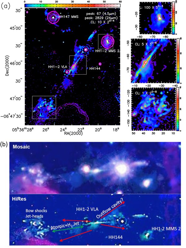
HH1-2: (a) The 4.5 μm and 24 μm HiRes deconvolved images. The MIPS 24 μm image is overlaid as contours on the IRAC 4.5 μm gray scale image. A square root color stretch is used to bring out low and high brightness emissions and the contour levels are in increments of factors of two or larger as indicated. The peak intensities (in units of MJy Sr–1) in the protostar/jet-outflow are indicated. The panels to the right show blowups of the selected regions highlighted by boxes in the left panel. The atomic jet features, traced by the atomic and/or ionic line emissions within the MIPS 24 μm band are identified by the 24 μm contours overlaid on the 4.5 μm gray scale image. (b) 3-color representation of HiRes deconvolved Spitzer IRAC images (lower panel): IRAC 3.6 μm (blue), 4.5 μm (green), 8.0 μm (red). The mosaic images are shown in the upper panel. The images are re-orientated to conserve space and the orientation in the sky is easily inferred from panel (a) above. In the 3-color representation the wide angle outflows are identified by the blue excess while the h2 jets and bow shocks by the green excess. The h2 jets (green arrows) and the wide angle cavity (red arrows) inferred from scatted light are indicated (not to scale).

